
Removing and Installing Wheels and TiresTypical Tools and Supplies Needed
Wheel RemovalThis article will discuss the removal and installation of tires.
The wheel must be removed to replace the tube and tire. If possible, begin by mounting bike in stand. If no stand is available, bike should be laid on its left, non-derailleur, and side when the rear wheel is removed. Do not stand bike upright without the rear wheel in place, as this will damage the rear derailleur. 1. Rear wheels: shift derailleur to outermost gear and innermost front chainring. |
||||
|
|
||||
|
|
||||
|
|
||||
|
||||
|
|
||||
|
|
||||
|
|
||||
|
6. Remove second bead from rim, which removes tire completely from rim. To fully inspect the tube and tire, it is best to remove both completely. |
||||
|
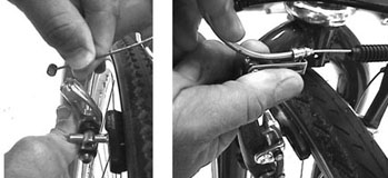
 4. Front wheels: guide wheel down and out of
fork. For rear wheels, pull back on rear derailleur to allow cogs to clear
chain. Lower wheel, guiding the wheel down through brake pads and forward
to clear chain and derailleur. Guide the wheel through the brake pads
and out the fork ends.
4. Front wheels: guide wheel down and out of
fork. For rear wheels, pull back on rear derailleur to allow cogs to clear
chain. Lower wheel, guiding the wheel down through brake pads and forward
to clear chain and derailleur. Guide the wheel through the brake pads
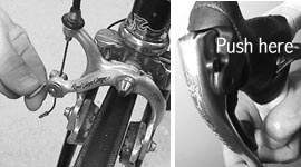
and out the fork ends. 2. Push one
bead of tire toward rim center. The tire bead will be pressed tight against
rim. Pushing it inwards loosens the bead from the rim. Repeat on other
bead.
2. Push one
bead of tire toward rim center. The tire bead will be pressed tight against
rim. Pushing it inwards loosens the bead from the rim. Repeat on other
bead.  3. Engage one tire lever under bead of tire.
Engage second lever 1-2" (25-50mm) from first lever then pull both levers
toward spokes to lift bead off rim. Disengage one lever. Move it two inches
(5cm) along the rim and re-engage lever in the bead. Pull lever to lift
next section of bead off rim.
3. Engage one tire lever under bead of tire.
Engage second lever 1-2" (25-50mm) from first lever then pull both levers
toward spokes to lift bead off rim. Disengage one lever. Move it two inches
(5cm) along the rim and re-engage lever in the bead. Pull lever to lift
next section of bead off rim.  4. Repeat engaging
the lever until the bead loosens. Then slide the lever along the rim under
the bead.
4. Repeat engaging
the lever until the bead loosens. Then slide the lever along the rim under
the bead. 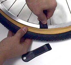 |
 |
|
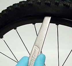
Some tires remove easier with a thinner and wider lever such as the TL-2 |
Some tire and rim combinations require a very strong steel lever, such as the TL-5. |
Inspecting the inner tube
When servicing a flat tire, always inspect tire and tube carefully to locate the cause of failure. This will help prevent future flats from the same cause.
1. Re-inflate inner tube if possible. Inflate until tube is twice its normal width.
2. Inspect for air leaks by holding tube close to the sensitive skin of lips or by holding tube near your ear to hear leaks. Move the tube around its circumference. If these steps do not work, submerge tube in water and watch for bubbles at the hole.
3. If you plan to repair the inner tube, use a marking pen to mark hole. Make four marks, one to each side of hole. Do not mark close to hole, as the mark may be sanded off.
The type of cut or hole in the tube will help determine the cause of the flat. Common causes of tire and tube failures are:
- Cut at valve core, commonly from misalignment of tube in rim or riding with low pressure. Be sure tube is mounted straight in rim and check pressure before rides.
- Leaky valve core, tighten with a valve core tool. More common with Schrader type valves, but also possible on some Presta valves.
- Blow causing a large shredded hole. These are usually not repairable. Check tire and rim as well for damage.
- Hole on inside edge of tube indicates a problem inside the rim, such as from rim strip failure, a protruding spoke or other sharp object inside the rim.
- A long cut or rip may indicate a tire blow out. Typically this is not repairable. Use care when seating tire during installation.
- A single puncture or small hole is commonly from a thorn, wire, or small nail. These may be repairable. Check tire as well for thorn, etc.
- Double slits are commonly from a rim pinch. The tube was pinched between rim and object in road/trail. Increase air pressure or use wider tires.
- V-shaped slits may be from nails or glass.
Inspecting the Tire
It is important to always inspect the tire as well as the inner tube. The cause of the flat, such as a nail or piece of glass may still be embedded in the tire or tread. Inspect both the outside of the rubber tread and the inside of the casing.
 1. Inspect outside of tread for protruding
nails, pieces of glass, thorns, or other objects. Squeeze any cut to look
inside for objects such as slivers of glass.
1. Inspect outside of tread for protruding
nails, pieces of glass, thorns, or other objects. Squeeze any cut to look
inside for objects such as slivers of glass.
2. Visually inspect inside of tire casing for nails, glass or debris. Wipe inside of casing with a rag, and then carefully feel inside with fingers.
3. Inspect sidewall for rips, holes, or damaged rubber and casing.
4. Inspect wire or fabric tire bead for damage.
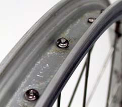
Rim Strip and Rim Cavity
The wheel rim is made with holes between the rim sidewalls for spoke nipples. A rim strip covers the holes or nipples. The rim strip can be made out of different materials such as cloth, rubber, or polyurethane plastic. The strip protects the inner tube from sharp edges in the base of the rim and from spoke ends and nipples that might puncture the tube.
Inspect inside the rim cavity, looking at the rim strip and for any sharp corners or protuding spokes.
 |
 |
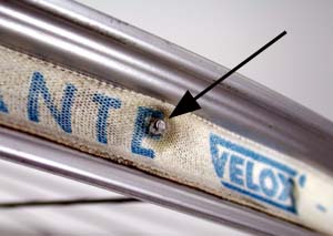
 The rim strip should
be wide enough to cover the bottom of the rim, but not so wide it interferes
with the seating of the tire bead. Inspect the rim strip whenever changing
a tire or inner tube. Look for tares and rips, and make sure rim strip
is centered over the nipple holes. In the image left, the rim holes are
exposed, which may cause a flat tire.
The rim strip should
be wide enough to cover the bottom of the rim, but not so wide it interferes
with the seating of the tire bead. Inspect the rim strip whenever changing
a tire or inner tube. Look for tares and rips, and make sure rim strip
is centered over the nipple holes. In the image left, the rim holes are
exposed, which may cause a flat tire.
Repairing Inner Tube
Simply replacing the punctured inner tube with a new tube is always the safest and most reliable procedure. However, it is possible in some cases to repair a small hole in an inner tube. If the hole is quite large, it may not be possible to repair. When in doubt replace the tube.
The GP-2 Super Patch Kit uses pre-glue patches. There is no tube of glue to leak or dry up. The VP-1 uses a vulcanizing fluid to bond the patch to the inner tube.
Installing Tire and Tube on Wheel
1. Note directional arrows of tire manufacturer, if any. Directional arrows printed on the sidewalls indicate rotation of wheel. Not all tires have direction orientation.
2. Inflate tube enough for tube to just hold its shape.
3. Install tube inside tire. Install with tube valve adjacent to air pressure recommendations written on tire sidewall.
4. Lower tire and valve into rim valve hole and align valve so it is pointing straight toward hub. A crooked valve can lead to a flat tire later.
 5.
Install one bead at a time. Work tire bead onto rim with hands. If tire
bead will not seat using hand, use tire lever as a last resort. Use caution
when using tire levers to avoid pinching inner tube. Engage tire lever
using same orientation as removing bead.
5.
Install one bead at a time. Work tire bead onto rim with hands. If tire
bead will not seat using hand, use tire lever as a last resort. Use caution
when using tire levers to avoid pinching inner tube. Engage tire lever
using same orientation as removing bead.
6. Work tube over rim sidewall and into rim cavity.
7. Install second bead onto rim. Use care if using a tire lever.
8. Inspect both sides of tire for bead seating and for any sign of the inner tube sticking out. Re-install if necessary.
 9.
Inflate to low pressure and inspect bead again on both sides. Look for
small molding line above bead. This line should run consistently above
rim.
9.
Inflate to low pressure and inspect bead again on both sides. Look for
small molding line above bead. This line should run consistently above
rim.
10. Inflate to full pressure and check with pressure gauge. It may be necessary to press downward above the valve in order to engage the pump head. For fully threaded valve shafts, re-install the locking nut, if any. Do not use wrench or pliers to tighten nut. Tighten finger tight.
Installing Wheel on Bike
The wheels must be properly mounted to the bicycle frame. Misalignment can result in problems with shifting and bike handling. If the wheel is not securely mounted in the dropouts, it may come out when the bike is ridden, possibly causing injury to the rider.
Quick release wheels use a hollow hub axle fitted with a shaft, a lever that operates a cam mechanism, and an adjusting nut. The cam puts tension on the shaft and pulls both the cam and the adjusting nut tight against the dropouts. This tension is what holds the wheel securely to the frame. The adjusting nut determines the amount of tension on the quick release lever and cam. Lubricate the cam mechanism if it appears sticky or dry.
The quick release is fitted with two conical shaped springs. The small end of the spring faces the axle, and the large end faces outward. These springs make the wheel easier to install. If one or both springs become twisted or damaged they may be removed. The springs serve no purpose once the wheel is tight on the bike.
Non-quick release hubs use axle nuts outside the dropouts. The axle nut will have a washer built into the nut, or a separate washer. If the washer has teeth or knurling, these face the dropout to help secure the wheel. Lubricate the axle threads while the wheel is off the bike.
It is often easiest to install the front wheel when the bike is standing on the ground. The quick release skewer must be fully engaged on the dropout surfaces. By placing the bike on the ground, the axle will be fully up in the dropouts.
1. Check that the quick release skewer lever is in open position.
Check that brake quick release mechanism is open.
2. Install front wheel between dropouts with skewer on left side (from rider's point of view). Pull wheel fully up into dropouts. For non-quick release wheels with axle nuts, washers go to outside of dropouts.
3. Rear wheels, pull back on rear derailleur to open chain. Place smallest cog between upper and lower sections of chain. Guide wheel between brake pads and engage smallest cog on chain.
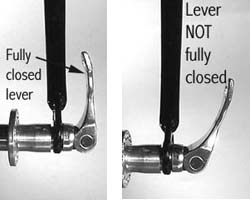
 4. Determine
final closing position of hub quick release lever. Rotate front lever
and adjusting nut so the lever will end up just in front of fork. Position
the rear lever so it falls between the chain stay and seat stays. Reposition
the lever as necessary if it will not fully close.
4. Determine
final closing position of hub quick release lever. Rotate front lever
and adjusting nut so the lever will end up just in front of fork. Position
the rear lever so it falls between the chain stay and seat stays. Reposition
the lever as necessary if it will not fully close.
 |
 |
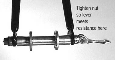
5. Adjust closing tension of quick release skewer. For most skewers, hold lever parallel to the hub axle, which is half way through its swing from fully open to fully closed. Tighten adjusting nut snug against dropout. Check results by moving lever back and forth through its swing. Lever should meet resistance to closing half way through its swing.
Close lever fully.
6. For non-quick release wheels, tighten axle nuts fully.
7. Close brake quick-release mechanism. View wheel centering in fork. Wheel should be centered between fork blades. To adjust wheel centering, open skewer, move wheel either left or right until wheel appears centered, then close skewer. For non-quick release wheels, loosen axle nuts and center wheel, then re-tighten nuts.
8. Inspect brake pad alignment and centering by closing and opening pads with brake lever. If brake pads are not centered to wheel, see Chapter 6, Brake Systems. If wheel fails to adequately center in frame, either the frame or wheel may be misaligned.
9. Spin wheel and double check pad alignment to rim. Be sure pads do not strike tire.
10. Orient skewer so lever will end up between the seat stay and chain stay, unless this prevents lever from fully closing.
11. Close brake quick release or attach MTB brake release wire.
 |
 |
12. View centering of wheel between chain stays and seat stays. Also sight rim centering to brake pads. Open skewer or loosen axle nuts and adjust as necessary to center wheel in frame. If brake pads are not adequately centered to wheel re-adjust brakes. If further attempts to align the wheel fail to adequately center it in frame, either the frame or wheel may be miss aligned. Seek a professional mechanic for help.
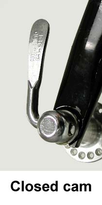
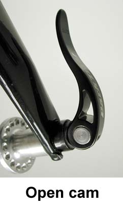
Note: So-called "open cam" skewers may require more tension from
the skewer. These skewer levers have the cam mechanism exposed, and should
be lubricated often. Always check with skewer manufacturer for specific
procedures.
Temporary repair of tire with tire boot
If the tire has been ripped and the casing damaged, it may not hold an inner tube. It is possible in some cases to make a temporary repair with a Tire Boot. A booted tire should not be considered a permanent repair. The tire should be replaced as soon as possible.

Locate rip in tire. Compare rip to size of tire boot. Tire boot must completely overlap rip to be effective. Wipe clean inside of tire adjacent to rip. Peal off backing of TB-1. Align patch so edges do not extend beyond tire bead. If necessary, cut boot so it does not extend past tire bead. Press patch to inside of casing.
Always replace ripped tires as soon as possible.
Suggested Park
Tools
- PCS-1 or PCS-4 Repair Stand
- Tire levers TL-1, TL-2, TL-5, or body of various take-a-long tools. For professional use, TL-10.
- Patch Kit such as the GP-2, or VP-1.
- Air pump PFP-2 or PFP-3, hand pump, or air compressor