


Hub Bearing Overhaul and AdjustmentLevel of Difficulty: Intermediate Typical Tools and Supplies Needed [1]
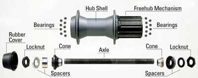
This article will discuss the adjustment and overhaul of "cup-and-cone" hubs. These hubs allow for access to internal bearings, and are adjustable. See related articles: Bicycle hubs may be either the adjustable cup-and-cone type or the non-adjustable cartridge style. The adjustable type bearing surfaces can be adjusted for bearing play. The cartridge types typically cannot be adjusted for wear or play. Both types can come in either the freehub type or the thread-on freewheel style. |
||||
|
||||
|
||||
Cartridge Bearing Hubs
Hubs using the cartridge type bearings are not serviceable in the sense they can be dismantled and adjusted. As cartridge bearings wear and develop play, the entire cartridge unit is replaced. Cartridge hub service is not covered in this article. |
||||
|
||||
|
|
||||
|
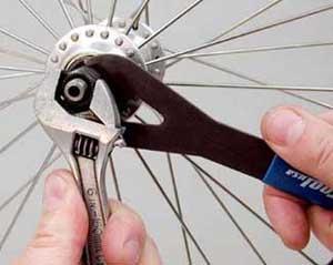
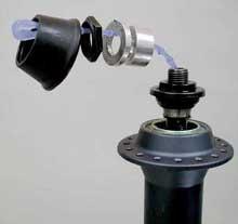
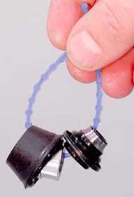
4 Remove any rubber cover. Use a tie or string to hold small parts in the same orientation as they came off of hub. |
||||
|
|
||||
|
|
||||
|
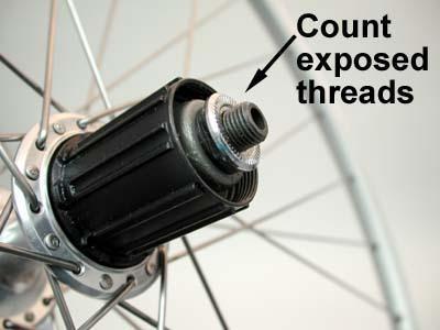
8 Place hand below right side, and lift wheel slowly. Be prepared to catch bearings that fall from hub. Place wheel on bench. 9 If inspecting bent axle, remove right side locknut and cones. Note that left side and right side cones, washers and locknuts may be different. Do not confuse left and right side parts. Use tie method to keep track of parts. Also note axle thread may be asymmetrical. The side with more axle spacers gets more axle thread. |
||||
|
|
||||
|
12 Wipe and clean all parts. Parts must be dry for assembly. Wipe freehub mechanism out using damp rag. Do not soak freehub in solvent. Freehub bodies are lubricated internally with a light lubricant, and soaking them with solvent will remove lubrication. For freehub service, see Freehub Service. |
||||
|
||||
|
|
||||
|
|
||||
|
||||
|
|
||||
|
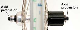
4 Install axle through right side of hub. 5 Install left side axle parts, using care to install in the same orientation as they came off. Do not set axle protrusion on this side and do not tighten locknut at this time. 6 For quick release type hubs, snug the cone down until it contacts the ball bearings, and turn back counter-clockwise one quarter turn (90 degrees). This will purposely make the bearing adjustment too loose. Hold cone with cone wrench and tighten locknut fully. Proceed to Hub adjustment below. |
||||
|
||||
|
||||
|
||||
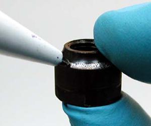
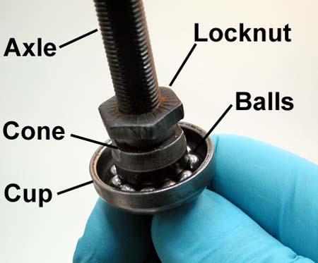 A basic bearing system is shown left. The cup is normally a permanent
press fit into the hub shell. The cone traps the ball bearing. The locknut
is tightened against the cone to prevent the cone from moving. If there
is looseness from bearing play, the cone can be move closer to the cup.
A basic bearing system is shown left. The cup is normally a permanent
press fit into the hub shell. The cone traps the ball bearing. The locknut
is tightened against the cone to prevent the cone from moving. If there
is looseness from bearing play, the cone can be move closer to the cup.
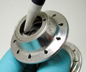
 7 Remove cone by turning counter-clockwise.
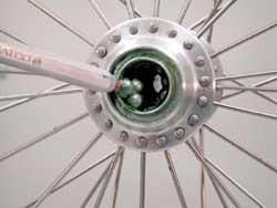
 2
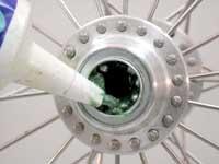
Grease heavily inside hub shell cups. Place ball bearings in both
cups and cover with more grease. Make sure balls are seated flat in cup.
For rear hubs, the common number is 9 balls of 1/4-inch diameter per side.
For front hubs, the common number is 10 balls of 3/16-inch diameter per
side.
2
Grease heavily inside hub shell cups. Place ball bearings in both
cups and cover with more grease. Make sure balls are seated flat in cup.
For rear hubs, the common number is 9 balls of 1/4-inch diameter per side.
For front hubs, the common number is 10 balls of 3/16-inch diameter per
side. 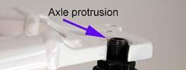
 |
 |
|
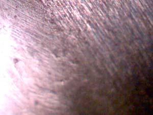
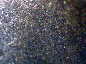
Bearing surfaces are made from hardened steel. The surfaces are cut typically by grinding. Round ball bearings roll on the curved surface of the cup and cone. Even the highest quality bearing surfaces will have slight grinding marks. In the left image above is a high quality cone magnified two hundred times. Notice the parallel marks from the grinding stone. Also note a slight pit from wear. The right hand image is a bearing magnified the same amount. It does show some surface marking, but is generally smoother than the cone or cup. Bearing surface smoothness will vary between manufacturers and between models. Some bearing system will simply "feel" smoother because they are smoother. This is why it is difficult to adjust by using a subjective feeling of smoothness. Generally, adjust bearings for the loosest setting that has no knocking or play, regardless of this relative smoothness. |
|
The following adjustment procedures simulate the on-the-bike compression while still allowing access to the left side cone and locknut for adjustment. The bicycle frame and skewer act as a holder for the wheel and the axle. The set up of the wheel on the frame may seem unusual. Follow directions carefully. An alternative to the procedure below is to adjust the bearings with the wheel unclamped. Mount the wheel in the frame to test the adjustment. Remove as necessary, adjust, and re-test.
1 Mount bike in repair stand.
2 Remove rear wheel from bike. If adjusting front wheel, remove front wheel as well.
3 Remove quick release skewer and springs. Remove any rubber boot covering left side cones and locknuts.
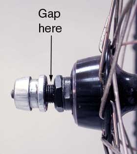 4
Insert skewer through cog side of hub. Install quick release adjusting
nut on non-cog side. There must be a gap between the skewer adjusting
nut and the locknut. The quick release nut must press only on the axle,
not on the locknut.
4
Insert skewer through cog side of hub. Install quick release adjusting
nut on non-cog side. There must be a gap between the skewer adjusting
nut and the locknut. The quick release nut must press only on the axle,
not on the locknut.
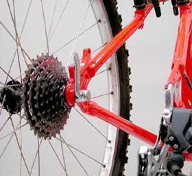 5
Place cog side of wheel into left rear dropout. Non-cog side sits
outboard of the bike, and is accessible to mechanic. If the cogs touch
or interfere with the frame, remove rear cogs. Front wheel: either left
or right side goes to rear dropout. Adjustment is done from side opposite
clamped side.
5
Place cog side of wheel into left rear dropout. Non-cog side sits
outboard of the bike, and is accessible to mechanic. If the cogs touch
or interfere with the frame, remove rear cogs. Front wheel: either left
or right side goes to rear dropout. Adjustment is done from side opposite
clamped side.
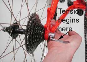 6 Adjust quick release until tension is same as when normally clamping
wheel in bike. Resistance to closing should begin half way through swing
to fully closed. If in doubt see Wheel
Installation.
6 Adjust quick release until tension is same as when normally clamping
wheel in bike. Resistance to closing should begin half way through swing
to fully closed. If in doubt see Wheel
Installation.
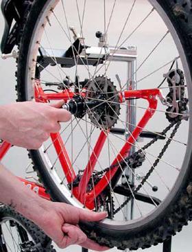 7 Check bearings for play. Hold end of axle on non-cog side with
one hand and rock rim laterally with other hand. Play in bearings will
be felt as a knocking in the axle. If play is felt, proceed to step #9
below.
7 Check bearings for play. Hold end of axle on non-cog side with
one hand and rock rim laterally with other hand. Play in bearings will
be felt as a knocking in the axle. If play is felt, proceed to step #9
below.
8 If no play is felt, adjustment is potentially too tight. Purposely
create excess bearing play as the first step to proper adjustment:
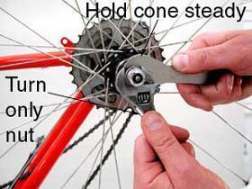 A.
Use a cone wrench and hold cone from moving. Note position and angle
of wrench.
A.
Use a cone wrench and hold cone from moving. Note position and angle
of wrench.
B. Use another wrench on locknut. Turn locknut counter-clockwise
to loosen.
C. Loosen cone by turning cone wrench counter-clockwise about 1/4
turn, or 90 degrees.
D. Hold cone from moving with cone wrench and tighten locknut.
Locknut must be fully tight before play can be checked.
E. Test for play by holding axle and moving rim laterally.
9 If play is felt, adjustment is too loose. Tighten adjustment:
 A.
Use a cone wrench and hold cone from moving. Note position and angle
of wrench.
A.
Use a cone wrench and hold cone from moving. Note position and angle
of wrench.
B. Use another wrench on locknut and loosen by turning counter-clockwise.
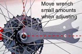
C. Recall angle of cone wrench and tighten adjustment by turning
cone clockwise 1/32nd of a turn. Imagine cone wrench extending to the
rim. Move end of wrench only the distance from one nipple to the next
at the rim. This approximates 1/32nd of a turn for thirty-six and thirty-two
spoke rims.
D. Hold cone from moving with cone wrench and tighten locknut.
Locknut must be fully tight before play can be checked.
10 Test again for play by holding axle with one hand and moving
rim laterally with the other hand. Rotate wheel and check for play all
the way around wheel rotation.
11 If play is still present, repeat adjustment step above until play just disappears. Remember to make small adjustments clockwise one at a time. Check for play at rim after each adjustment. It is likely it will take several small adjustments.
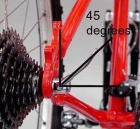 12
Once play has disappeared, test final adjustment. Open skewer partially
(about 45 degrees) and check again for play by rotating wheel and checking
several points. If play is felt during this test, hub is adjusted.
12
Once play has disappeared, test final adjustment. Open skewer partially
(about 45 degrees) and check again for play by rotating wheel and checking
several points. If play is felt during this test, hub is adjusted.
13 If no play is felt during final skewer check, the adjustment is too tight. To adjust, first CLOSE SKEWER, loosen locknut and loosen adjustment only slightly. Tighten locknut and check adjustment for play, then test again by opening skewer to 45-degreee. Adjustment is finished when there is no play felt when skewer is closed, but some play is felt when skewer is partially open.
14 Remove wheel from bike and return skewer and springs to normal position. Replace any rubber covers. Notice there is play in axle. This play disappears when wheel is clamped in place for use. You must use the same skewer setting for riding as for adjusting the hub.
15 Remount cogs, if removed, and install wheel into bike. It is necessary to duplicate the quick release setting of hub adjustment when installing wheel.
Misc. Notes: If hub will not adjust smoothly, the bearing surfaces may be worn out. If play does not disappear until bearing adjustment is very tight, right side locknut may not be tight against cone, or cups inside hub shell may be loose.
Hub adjustment - Solid axle type
Non-quick release hub systems use axle nuts and washers on the outside of the dropouts to hold the wheel in place. Adjustment of solid axle hub bearings is similar to the hollow axle quick release type, but there is no need to allow for axle flex. Mount the wheel in the frame similar to quick release hubs as described above. Tighten the axle nut inside the dropout that is holding the wheel. The axle is now held tight. Check for bearing play. If no play is present, create play by loosening bearing adjustment, then adjust in small increments until play in gone. The goal is to find the loosest adjustment that has no play. Remove the wheel from the bike. The adjustment for solid axle hubs does not change when mounted in the bike.
Cartridge bearing hubs
These types of hubs use an industrial-type bearing unit. The inner and outer rotating races and ball bearings are installed as a unit. These hubs are not serviceable in the sense they are overhauled and adjusted. When the cartridge bearings are worn, rough, or have play, the cartridge should be replaced. The bearing unit is then removed and a new one pressed in. This requires special tools and is best left to professional mechanics.
Suggested Park Tools
- DCW and SCW series cone wrenches. Always use the smallest size that fits.
- AV-1, or AV-3 axle vise
- Park Tool Polylube® 1000 grease
- Solvent, such as Bio ChainBrite® solvent