

Removing and installing ISIS Drive® and Shimano® pipe billet spindle crankarmsLevel of Difficulty: Novice Typical tools & supplies [1]
|
|
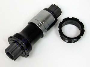
This article will discuss the removal and installation of crankarms on the round, splined type spindles. These are the ISIS Drive® or Shimano® Octalink types. For service of square-tapered type crankarms, see Square Tapered Spindle Type crankarms. See also Crank Tools. The oversized pipe billet splined spindles are round at the ends rather than square shaped. A series of internal splines in the crank are mated to external splines on the spindle. The cranks are held tightly to the spindle by tension from the crank bolt. Shimano® uses an 8-spline design called Octalink®. A different and non-interchangeable standard is the ISIS DRIVE® (International Spline Interface Standard). The ISIS DRIVE® system uses ten splines of a different shape from Shimano®. Again, the two systems do not interchange. |
|
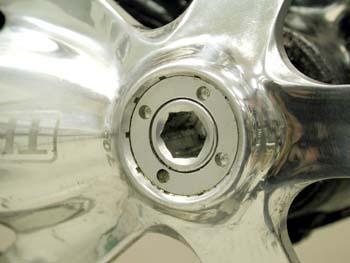
For all types of crankarms, the first step of removal is to turn the crank bolt counter-clockwise. Two things might happen. First, the bolt may simply come out. In this case, inspect inside the crankarm for the end of the spindle. Remove any washer seen inside. A square hole in the crankarm uses the square type spindle. In this case see Square Spindle-Type Crankarms. A round hole in the crankarm where it meets the spindle is the pipe billet type.
|
|
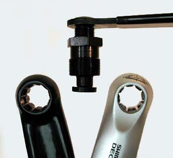
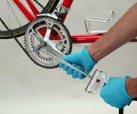
 The second possibility is the crankarm bolt presses back against a crankarm cap, or retaining ring, and the entire arm is pulled off. This is the case if the arm uses a One-Key-Release system. One-key-release systems use a metal cap threaded into the crankarm. This metal cap takes the place of the dust cap and surrounds the crankarm bolt head. To remove the crankarm, leave the ring in place. Turn the crankarm bolt counter-clockwise and the bolt backs against the ring pulling the arm from the spindle. Both oversized pipe billet spindle and square type spindle system may come with the one-key-release system, and both are removed the same way. It can occur that the one-key-release cap or retaining ring comes loose. To secure the ring use the Park Tool SPA-2 pin spanner. No crank extractor is required for the one-key-release system, as seen below. |
|
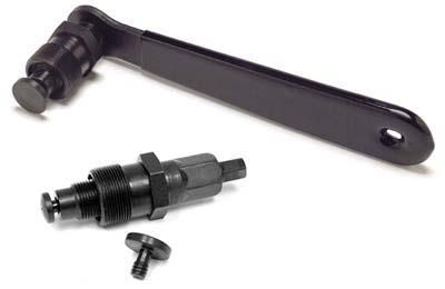
For oversized pipe billet crankarms not using the one-key-release system, such as some ISIS Drive® and some Shimano® systems, use Park Tool CWP-6, or CCP-4 |
|
|
|
Crankarm installation
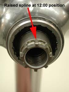
Use care when installing the crankarm to the spindle so splines match correctly. Crankarms using the one-key-release system make it difficult to see how the arm is fitting to the spindle. A forced mismatch on the splines can damage the arm. Splined type crankarms without the one-key system allow easy viewing of the spline fit. The spline pattern on the spindle consists of a series raised splines separated by flutes or recesses, at the minor diameter. 1 Grease threads inside bottom bracket spindle. Grease splines
on spindle. |
|
4 Tighten bolt fully. If possible use a torque wrench and secure
to 305-391 inch-pounds. |
|
|
|