


External Bearing Crankset System Installation and Removal
Shimano® Hollowtech II, Race Face® X-type Crankset and FSA® MegaeXo
Level of Difficulty: Intermediate
This article will discuss service of the "external bearing cranksets". These systems integrate the bottom bracket bearings, crank and spindle. The spindle is a permanent part of one arm. The opposite arm slides onto the spindle splines and is then secured. While conventional bottom bracket system have the bearing inside the bottom bracket shell, these types of cranksets have external bearings that sit outboard of the shell face. Example of these systems are Shimano® Hollowtech II, Race Face® X-type Crankset and FSA® MegaeXo, and Truvativ® Giga X Pipe.
Typical Tools and Supplies[1]
- Appropriate lockring wrench
- 5mm Hex Wrench
- Thread preparation, options include grease, anti-seize, and thread lockers
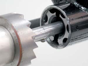
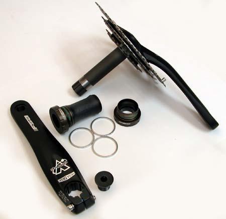
The external crankset bearing systems integrate the bearings, cranks and spindle. The bearings sit outside the face of the bottom bracket shell face. The spindle is a permanent part of one arm. The arm slides onto splines and is then secured. These systems use a cartridge bearing.
The bearings cups of these systems thread into the bottom bracket, and press against the shell face. The bearings then sit outside of the shell. It is important that the left and right shell surfaces are adequately machined square to the threads and one another. Miss aligned shell faces can cause the bearing cups to twist as the seat into the bike.
MTB-type cranksets
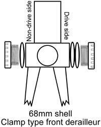
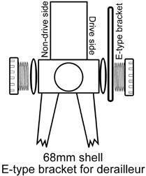
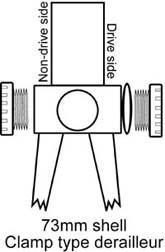
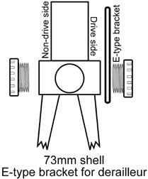
The table below outlines the spacer arrangement for the Shimano® XTR FC-M960, XT FC-M760, Saint FC-M800, Race Face® X-type, and FSA® MegaeXo bottom bracket bearings as installed into 68mm and 73mm shell widths. The E-type brackets and International Standard Chain Guide bracket options are also listed. The bearing cups are of a similar design, and cups are designed to be spaced 75.5mm apart. Three spacers of 2.5mm are supplied to achieve this width. E-type front derailleur brackets, or a chain guide mount, are counted toward the width total.
Bottom Bracket Shell Width
Front Derailleur or Chainguide
Non-Drive
(left side of bike)Drive Side (right side of bike)
68mm
Clamp on
2.5mm spacer
2 x 2.5mm spacers
68mm
E-type derailleur bracket
2.5mm spacer
2.5mm spacer plus E-type bracket
68mm
Chainguide system
2.5mm spacer
2.5mm spacer plus chainguide
73mm
Clamp-on
No spacer
2.5mm spacer
73mm
E-type front derailleur
No spacer
E-type bracket
73mm
Chainguide
No Spacer
International Standard Chain Guide bracket only
NOTE: The Shimano® FC-M761 is sometime used with a "crankcase" shifting system. More spacers are included for this model:
68mm shell band type: Left cup-2.5mm spacer Right cup-1 each of 2.5mm, 0.7mm, and 0.8mm
68mm shell chaincase stay type: Left cup-2.5mm spacer Right cup- chaincase stay, 0.7mm spacer, 2.5mm spacer
68mm E-type bracket: Left cup- 2.5mm spacer Right cup- E-type bracket, 2.5mm spacer, .8mm spacer
73mm band type: Left cup- no spacer Right cup- no spacer
73mm chaincase stay type: Left cup- no spacer Right cup- chaincase, 0.7mm spacer
73mm E-bracket type: Left cup- no spacer Right cup- E-bracket only
Road-type Cranksets
The Shimano® Dura-Ace FC-7800 crankset, Truvativ® and FSA® road cranksets are designed for a 68mm bottom bracket shell. No spacers are required or used for the road systems.
Frame Preparation
The bearing cups thread into the bottom bracket shell and press against the shell face. It is important that the left and right shell face surfaces be machined square to the threads and one another. If a bearing cup is secured to a shell with mis-aligned faces, the two bearings will not align properly with each other. Unlike conventional cartridge bottom brackets, these bearings use the shell face as a reference for alignment. Shell faces that are not parallel may cause a twist or load to the bearings. See Bottom Bracket Machining for details on facing and machining.
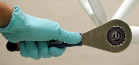
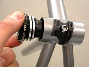
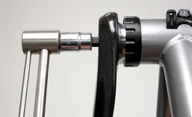
Prepare threads of shell with either grease, anti-seize, or a mild thread locker. For more on thread preparation, see Basic Thread Concepts. Install correct amount of spacers on cup marked with "R" (left-threaded cup) and install dust sleeve on cup. Thread cup counter-clockwise into right side (drive side) of bike. Use care not to cross thread cup. Tighten fully, approximately 305 to 435 inch pounds. When using the BBT-9, and grabbing the tool about 6-inches (15 cm) from the cup, apply about 60 pounds of effort (27 kilograms) of effort to tighten the cups.
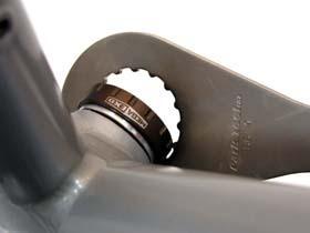
Install correct spacers as needed on cup marked “L” (right-threaded cup). Thread cup clockwise into left side (non-drive) of bike and tighten fully as before.
Shimano® Hollowtech II Procedures
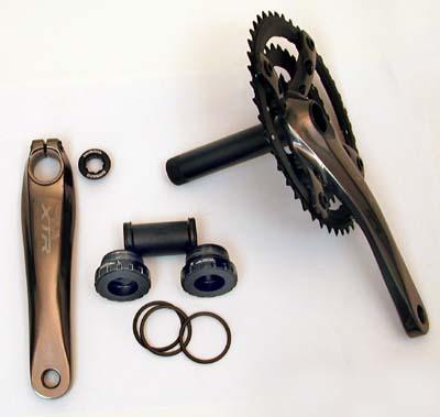
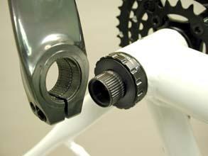
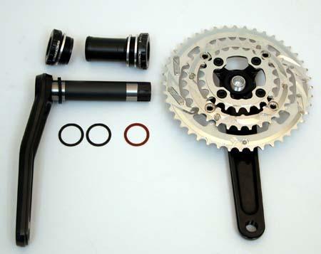
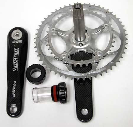
The Shimano® XTR FC-M960 Hollowtech II is seen below. The Dura-Ace system is similar in design, but uses different cups and no spacers. The right side arm contains the spindle. The left arm is secured with two pinch bolts. A crank cap is used on the left arm for bearing adjustment. The cap does not hold the crank, it is only for adjustment.
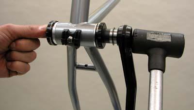
After bearing cups are installed, grease spindle surface and place right crank with spindle through the right side cup (drive side). Push from right side until spindle comes out left cup. Fit is snug, and in some cases gentle use of a mallet may help.
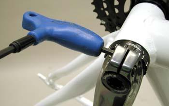
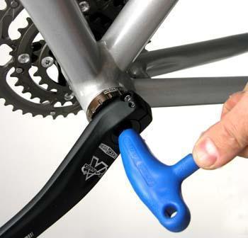
If spindle appears to catch and will not come out non-drive side cup, may be an indication that shell faces need machining. Grease splines of spindle and install left arm. Notice splines are keyed, and left arm will only install 180-degrees opposite of right arm. Grease threads of arm cap and thread cap into spindle. This cap acts only to push arm fully over to cup bearing. This cap does not tighten the arm onto the spindle. IMPORTANT NOTE: Secure cap gently. Use the eight sided stud a the end of the BBT-9 and tighten only 4 to 6 inch-pounds. Over tightening will side-load the bearing and cause premature wear. Spin arm to test.

Use a hex wrench and secure bolts at compression slot. Secure to 88 to 132 inch-pounds. Secure bolts evenly, working first one and then the other.
Disassembly
IMPORTANT NOTE: First, loosen the two left crank pinch bolts at end of arm. Next, loosen and remove arm cap and slide arm off. It it sometimes necessary to gently tap arm with mallet. Pull crankset to right to remove right arm and spindle. Use BBT-9 to remove both cups. Non-drive side removes counter-clockwise. Drive side removes clockwise.
FSA® MegaeXo Crankset
The FSA® system shares some of the same service features as the crankset previously described. The right side arm contains the spindle. The left arm is pressed gently against the bearing cups by the arm cap.
Begin by installing bottom bracket bearing cups as described above. The arrangement of spacers is the same as shown in the table. Grease spindle surface and press right crank through right side. The fit is snug, and mild use of a mallet may at times be useful. Place left arm on to spindle splines. Grease thread of crank cap and thread into spindle. Use a 8mm hex wrench and GENTLY snug the cap. The left cap simply bring the arm over to the bearing. It is used as a bearing adjustment, and it does not secure the right arm.
Secure the left crank with the pinch bolts in the arm. Alternately tighten each bolt until both are fully tight. Check arms for play.
Race Face® X-Type Service
Begin installation by installing bearing cups as describe
above for Shimano®, using the BBT-9.
Arrange cup spacers as described in the table above.
The left crank uses an elastomer washer that will preload the bearings. The chainline is adjusted with 1mm spacers. No spacers are used on the right arm to achieve the 48mm chainline. One spacer on the right arm will give a 49mm chainline, and two spaces a 50mm.
Grease spindle surface and install spindle through left side on bike after installing appropriate chainline washers. The fit of the spindle may be snug and some mild force may be necessary. Use a rubber mallet with care. Guide the spindle through the right cup, and install any needed chainline washers.
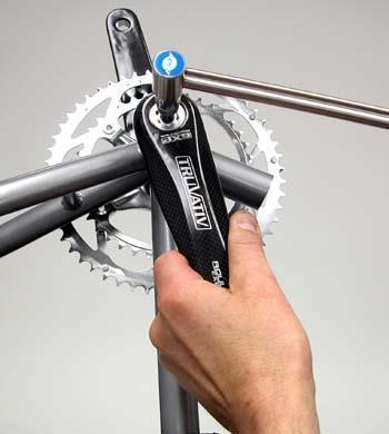
Grease internal threads of spindle, and grease spindle splines. Align right arm 180-degrees from left arm and begin to turn bolt clockwise using a 8mm hex wrench. Secure bolt to a torque of 360 inch-pounds to 600 inch-pounds. Bolt will come to a “hard stop” as the arm fully presses to spindle.
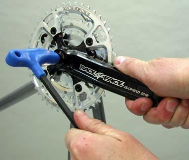
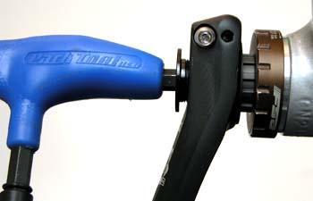
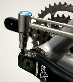
The X-type right side crank has a one-key release system. The retaining cap use a left-hand thread, and is secured to the arm with a 10mm hex wrench. It is not necessary to remove the one-key system. To remove the arm, use a 8mm hex wrench on the crank bolt and turn counter-clockwise. One-key system will remove arm from the spindle. After removing the right arm, pull the left arm to remove. It may be necessary to use a mallet and tap spindle to free the arm.
The image below shows the one-key system. It is not necessary to remove the system for either removal or installation.

Truvativ® Giga X Pipe
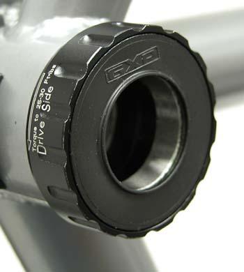
The Truvtiv® Giga X Pipe is a road-type crankset system. The bottom bracket cups are designed for the 68mm bottom bracket shell width. Cups are marked with thread direction arrows and torque specifications.
The spindle is a permanent press fit into the driveside arm. Each cup is tightened into the bottom bracket shell as with the systems above. No spacers are need or required.
Both cups are tighten to 300-360 inch-pounds. Grease the splines and surface of the spindle and insert through the right side cup. Install left arm and tighten. There is no "bearing adjustment". The drive side cup has a rubber lip that compresses as the arms are pressed. As the splined left arm is tightened, it compressed the lip.
Tighten left arm to 360 to 420 inch-pounds. The left arm has a one-key release system. No puller is required to remove, simply use 8mm hex wrench and turn crankbolt counter-clockwise.
Suggested Park Tools
- Park Tool BBT-9 lockring wrench
- 5mm Hex Wrench
- Thread preparation - Polylube® 1000 grease